Deck design · The Gap QLD
Structural drawings for a deck extension in The Gap QLD, with steel beams, timber joists, concrete piers and fixings to the existing house.
- Service
- Deck design
- Location
- The Gap QLD
- Completed
- October 2026
- Soil class designed for
- Class M (assumed, to be confirmed on site)
- Footings
- 450 mm mass-concrete piers
- Frame
- 230 PFC steel beams, MGP12 timber joists
The brief
The owners wanted to extend the existing deck along the side of their home in The Gap, with a new stair down to the yard. Their builder needed structural drawings showing how the new frame would be supported, and how it would connect to the house without overloading it.
What we designed
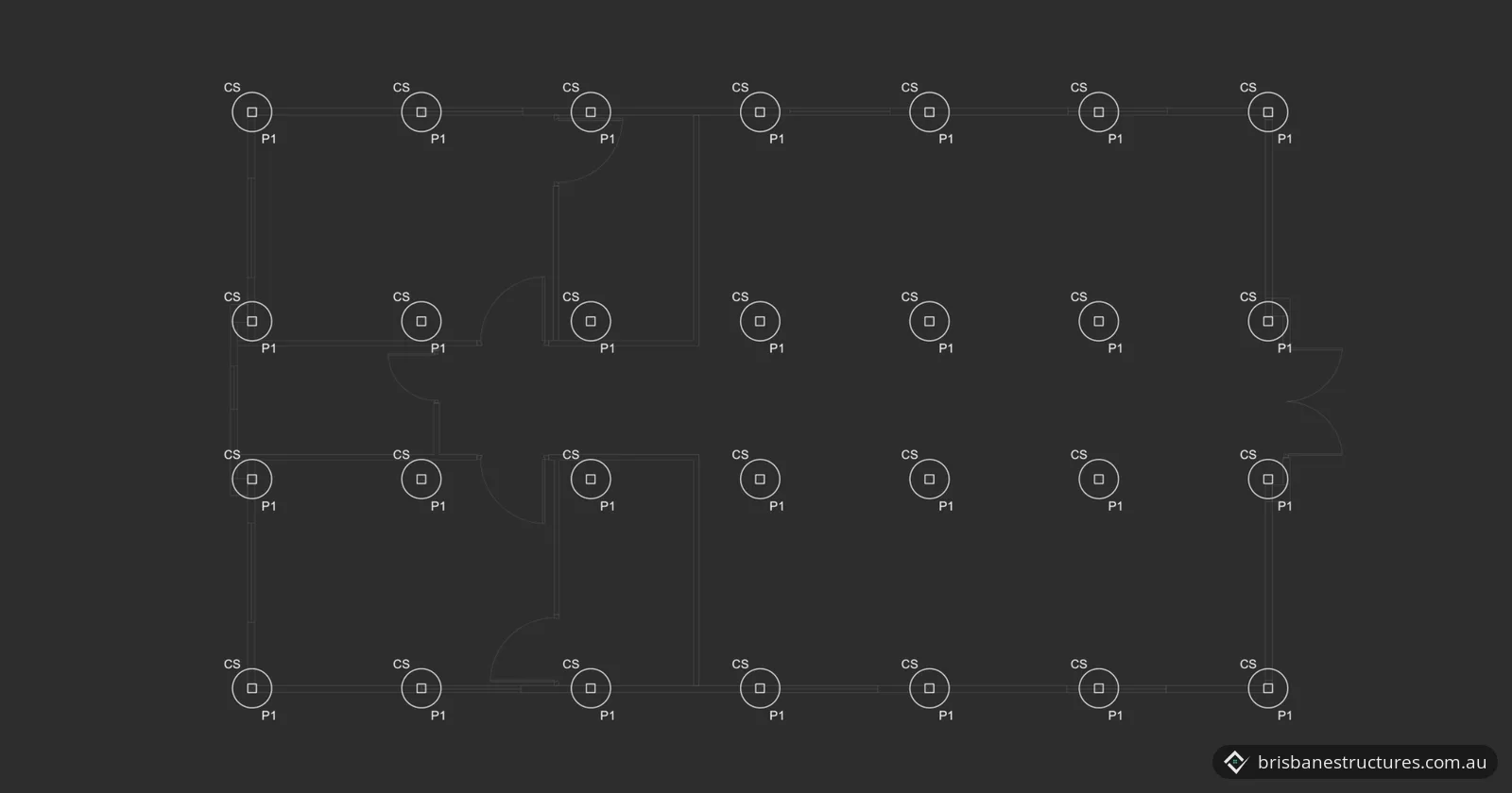
We prepared a full set of structural drawings: a cover sheet, general notes, a foundation layout, a framing layout and the connection details.
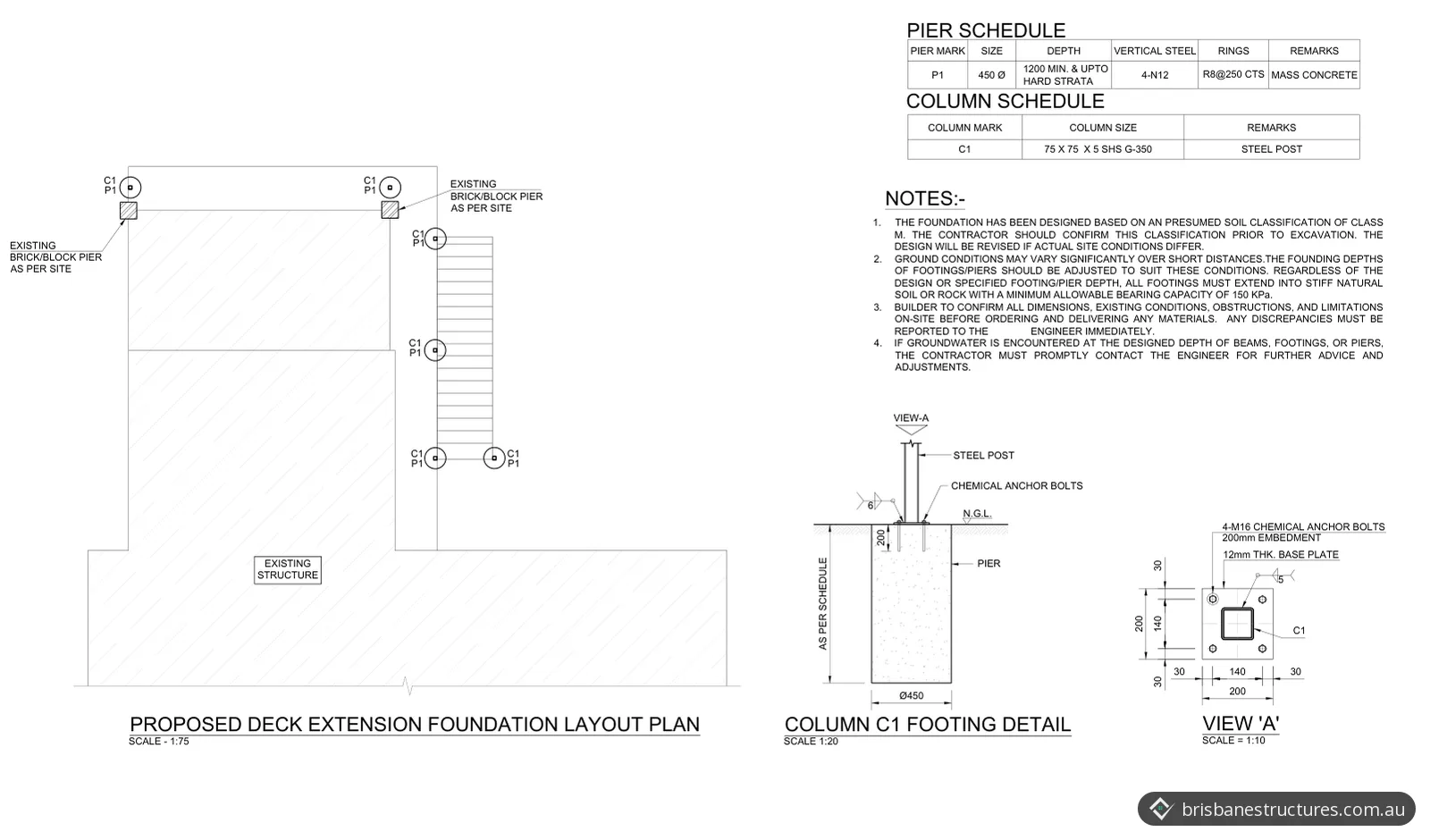
- Footings. Each new steel post sits on a 450 mm diameter mass-concrete pier, at least 1200 mm deep and taken down to hard ground. The design assumes a Class M (moderately reactive) site, and the notes ask the builder to confirm the soil before digging. Every footing has to reach stiff natural soil or rock with an allowable bearing capacity of at least 150 kPa.
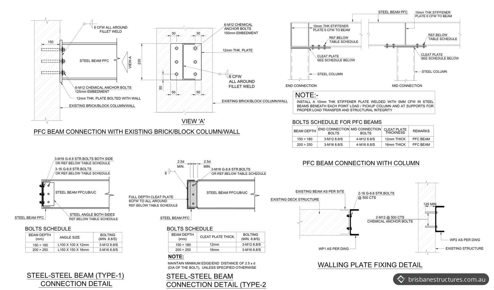
- Posts. 75 x 75 x 5 mm steel posts (Grade 350), each on a 12 mm base plate held down with four M16 chemical anchors set 200 mm into the pier.
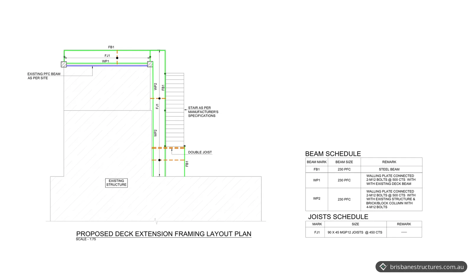
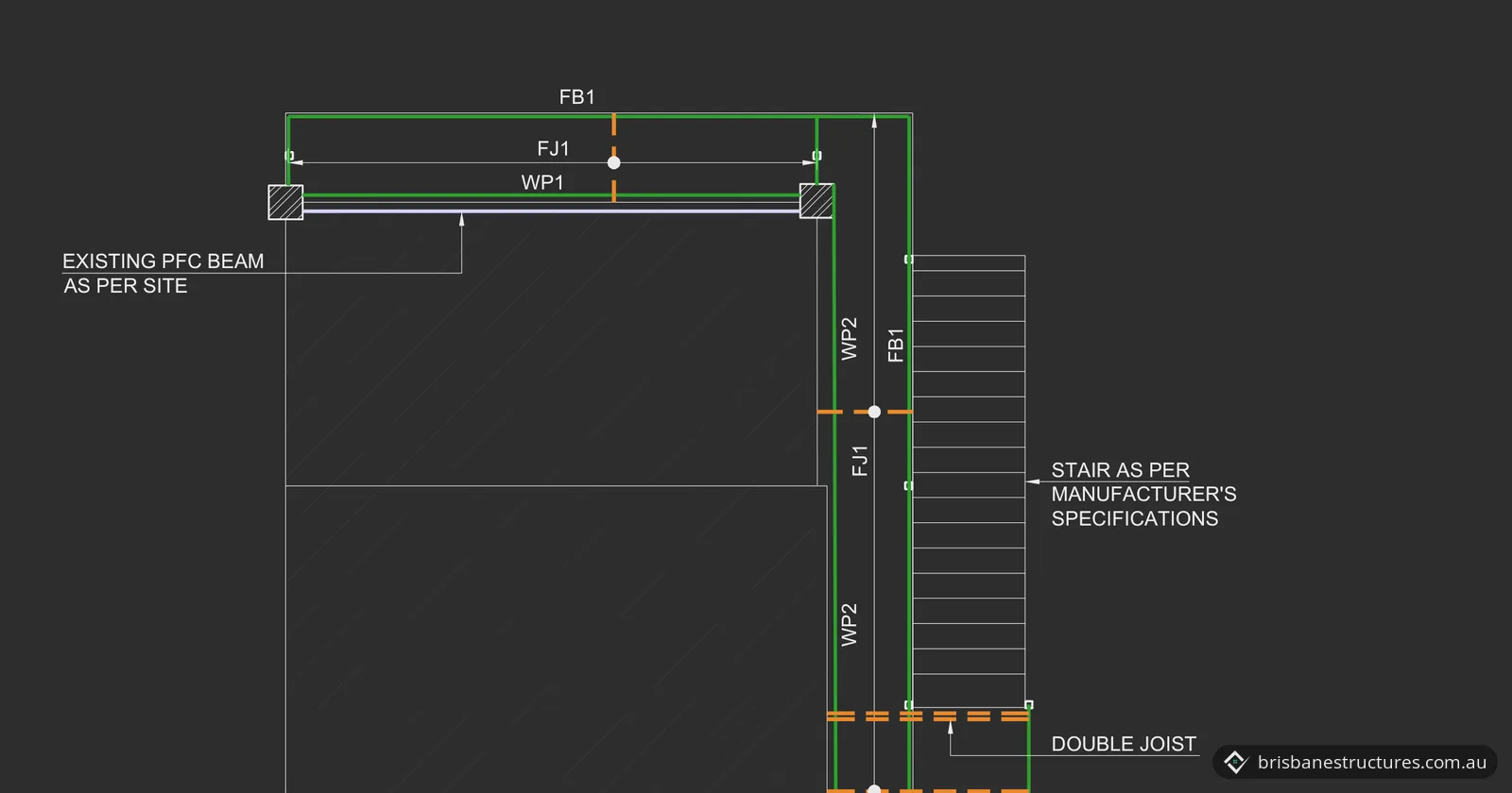
- Frame. 230 mm steel channel (PFC) beams carry 90 x 45 mm MGP12 timber joists at 450 mm centres, with a double joist at the stair.
- Connection to the house. Along the house, the new frame hangs off steel walling plates. They are bolted to the existing deck beam and to the brick and block walls with M12 bolts at 500 mm centres. Stiffener plates are welded into the beams wherever a post or point load lands.
The result
The finished drawings give the builder everything needed to price and build the extension: footing sizes and depths, every member size, and a detail for each connection to the existing structure.
Photos and drawings